


Alpha - Installation Guide
Alpha One Installation Guide

Setup Notes
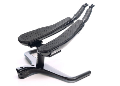
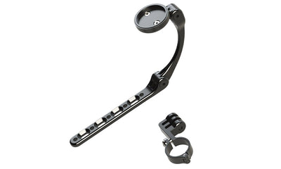
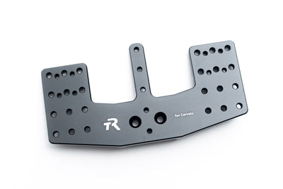
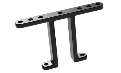
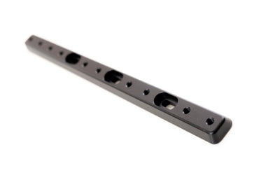
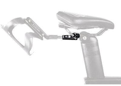
- Please refer to all part names indicated in the image above. These will be referenced throughout this Installation Guide.
- All bolts on Alpha One can be adjusted with a single 4mm hex wrench. We include a high-quality Silca 4mm wrench for easy on-the-fly adjustments. However, always use a torque wrench for initial installation, and whenever available. Overtorque can result in damage to the bar, not covered by warranty. However, the Silca wrench provided is a small one, unlikely to overtorque, and ideal for temporary on-the-road adjustments.
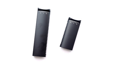
- Alpha One can accept any 22.2mm standard aerobar extension. It can be purchased with our own TriRig Gamma extensions which allow a variety of different positions to be achieved. However, it can also be purchased without any extensions so that you can use your own. Any standard extension may be used. Some older extensions use a 22.0mm diameter instead of the more common 22.2mm standard. These undersized extensions may be difficult to tighten down, and we cannot guarantee fit. However, we have successfully tested some 22.0mm extensions in the bar, and they fit well. So if you have a favorite extension in the 22.0mm standard, there's a good chance it will work in Alpha One.
Stem Hardware
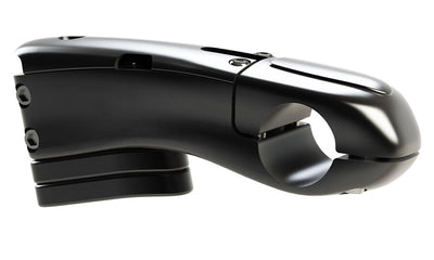
- Begin by removing the headset cap and any round spacers already on your fork. Alpha One is designed with aero-matched stem spacers and integrated dust cap for superior aerodynamic performance. The bottom surface of the base bar, and the aero-matched stem spacers all feature a 1.5mm counterbore to cover your headset, eliminating the need for a dust cover. However, if your particular setup requires its existing dust cover, or the Alpha One system does not adequately cover your headset, you can use the 1.5mm-thick Headset Spacer and use your existing dust cover. This part goes underneath your lowest stem spacer, or directly beneath the base bar if you are not using any stem spacers.
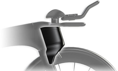
- Alpha One includes in integrated cable cover which requires you to trim your fork steerer. It can be used without this cable cover if you wish to keep spacers above your stem. However, for best aerodynamic and functional performance, you will want to trim your steerer tube and use the integrated cover. Trim your steerer tube so that it ends 2-3mm below the top surface of the Alpha One's integrated stem.
- With the cable cover removed, install Alpha One onto your fork as you would any other stem. Apply carbon paste around the steerer tube, and all interior surfaces of Alpha One stem clamping zone. Install the integrated cable cover, and follow the torque specification of your headset for the headset preload bolt (in general, just enough torque to remove any play from the steerer column). Then use 5-6 Nm of torque on the stem pinch bolts to tighten Alpha One to your steerer tube.
- Alpha One features advanced cable routing for use with any drivetrain, as well as centerpull brakes like the TriRig Omega X. The brake routing system features a removable cable stop so that you can either run bare cable to your brake with the stop in place, or run full housing or a hydraulic line by removing the cable stop.
Extension + Arm Cup Hardware
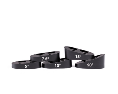
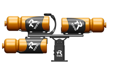
- Attach the Dragonfly to the Monopost, using the two M6 countersunk screws and the special Tilt Washer, with the Tilt Washer's arrow pointing forward toward the bicycle's front wheel. The angle of tilt is indicated by the hashmarks on the Monopost, and can be adjusted from approximately -10 to +17.5 degrees. Tighten both M6 countersunk screws to 8 Nm. The tilt angle can be adjusted or readjusted at any time, even with the arm cups in their narrowest position.
- Alpha One's Monopost allows for continuous stack adjustment. Adjust the stack height according to the Fit Guide and tighten the front set screw to 11-12 Nm (if you have the early generation carbon monopost, use 8-9nm). This adjustment can be changed at any time.
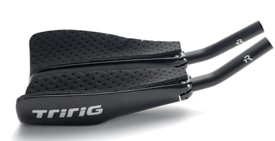
- Finally, slip the extensions into the Extension Clamps and tighten the two M4 screws to a torque of 4 Nm. Note that this is relatively low torque compared to many other aerobars. As with all bolts on the bar, we designed Alpha One Extension Clamps to provide a stable, secure grip without the need for unnecessarily high torque.
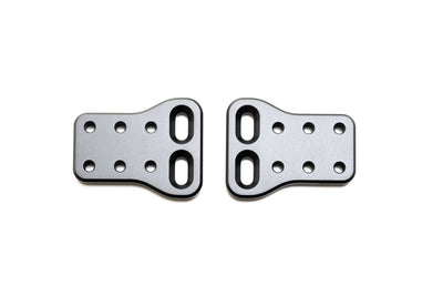
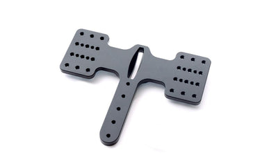
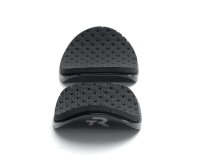
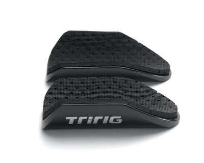
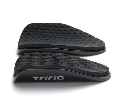
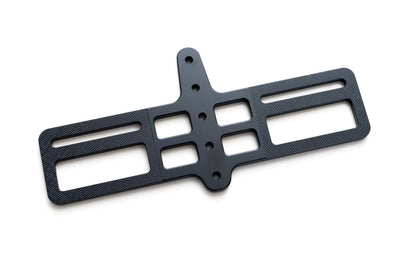
- Mount the arm cups via two M6 x 12mm bolts each. Note that although there are four bolts on the Dragonfly cup mount, only TWO are meant to be used at any time, as shown in the images below. This allows seven distinct pad stance width positions, and three pad reach positions. Note that in every pad position, you can access the Arm Cup bolts, Extension Clamp bolts, and Tilt bolts, at any time. There is ZERO bolt occlusion on Alpha One, meaning that all bolts are accessible at all times, and are never covered up by other pieces of hardware. This is true no matter how you have set up your bar.
Mechanical Cable Routing
- In general, cable routing is straightforward and self-explanatory. However, for mechanical cables, it can be helpful to leave the cables routed outside the extensions, in order to maximize your ability to make stack adjustments without needing to make any changes to the cable routing. Have a look at the images below to see our recommended method for the routing of mechanical shifter cables.

Remove cable cover, route cables.

Collect cables and align underneath cable cover

Replace cable cover

Final result

Housing outside extensions

Minimal frontal area, maximum adjustability
Alpha One Measurements:

Pads in rearward position

Pads in centered position

Pads in forward position

Pad stance width

Bar width is 400mm c-c

Arm cup specs